[<– previous section | next section –>]
0. Introduction

1. Basic Operation

2. The Conversion Overview

4. Main Components

5. Schematics

6. Arduino Code
A turntable for a zoetrope can be built from scratch or by recycling various electronic devices that have a motor strong enough to spin discs of the required size. Smaller turntables have for example been recycled from computer hard drives. In this project I re-purposed a 30 year old record player.
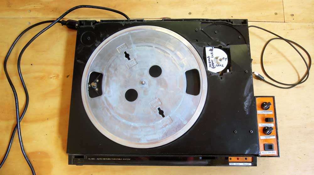
After taking off the bottom cover we’re looking at these relatively simple mechanical and electronic innards.
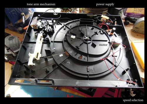
On the left side is the mechanism that couples the tone arm with the turntable via thin metal rods. Back-right is the small power transformer which simply provides current to the motor. The audio circuitry is passive and requires no external power. Front-right is a sliding switch to select 33.5 or 45 rotations per minute. 33.5 is for LPs and 45 for singles.
For the project we will only keep the motor, everything else will have to be taken out.
The motor speed here is selected by adding or bypassing a resistor via the sliding switch.
Since the disc for the zoetrope scene should be larger than a LP, the top part of the turntable case has to be leveled so that the disc can rotate freely. This is done with various tools such as a simple handsaw, a Dremel oscillating tool and a heat gun with a cutting attachment.
Top of the turntable after some creative material removal.
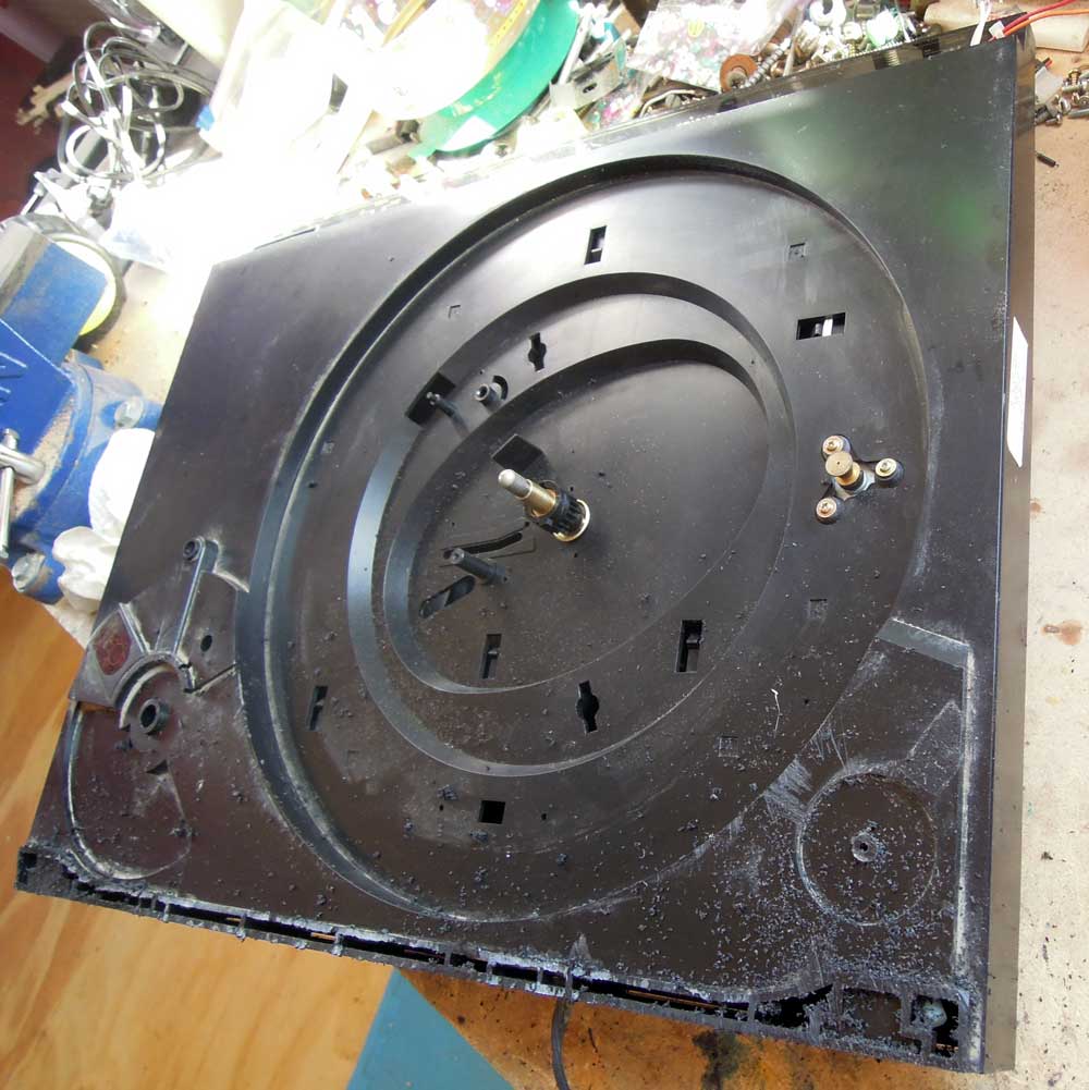
Stripped of the tone arm assembly and everything else except for the motor and the metal spindle.
Unfortunately the raised plastic ledge had to be crudely cut to allow the larger disc to spin freely.
The original power transformer only had to drive the motor with 12V DC. We will use an Arduino UNO for testing and ultimately a smaller Arduino Pro Mini for permanent installation. For this we need a better option as a power supply. A small computer power supply from a recently disassembled DVD drive was available. Like most computer PSUs, this has multiple 12V and 5V feeds, a connector for an ON/OFF switch and an LED to signal when it is powered on.
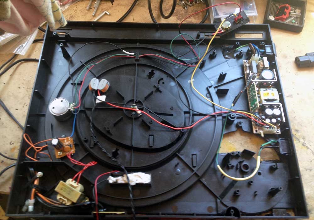
Even though this PSU is smaller than a regular PC PSU it was still a bit of a challenge to find a fitting location for in the relatively flat space inside the case.
Here, we have the new PSU on the right. The ON/OFF switch and power status LED are connected. You can also see the turntable speed control’s 10k potentiometer top-right. This replaces the fixed resistor.
The original 12V transformer is still supplying the motor at this stage.
While the speed adjustment is analog and requires no additional circuitry, the strobe light trigger and optical syncing needs a bit of computing power.
Here, an Arduino UNO is getting wired up to a photo resistor to test where and how the rotation of the disc can reliably trigger the strobe signal.
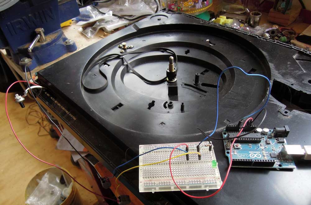
When experimenting with the Arduino, connections are usually made using short wires with wire plugs on either end. Additional external electronic components can be wired up using a breadboard.
The best spot for the optical components has been determined. This requires one white LED, which will illuminate the underside of the white, spinning scene disc. The disc is marked with thick black lines. While the disc is spinning, a photo-resistor will detect the light/dark pattern created by the consistent light source and the black lines. This will be processed in the Arduino and used to generate the automatic sync signal for the strobe.
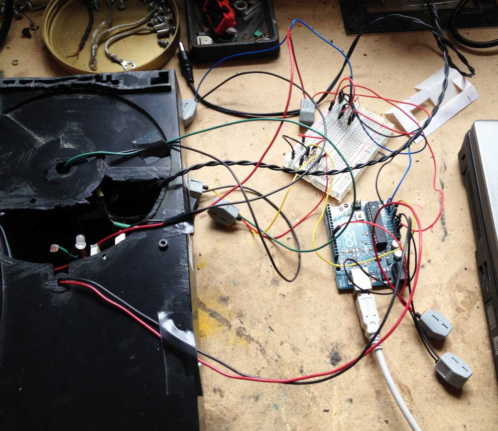
Here, the experimental setup is slowly growing. In the black case you can spot the white LED and right next to it the small photo-resistor. Both are just stuck in there at the moment and freely movable to find the best distance from the spinning disc.
You can see how many components are connected to the Arduino or the breadboard by those gray connectors.
At this stage it is very important to use consistent wire colors to be able to trace signal and power flows.
Also, the Arduino here is connected to a laptop via a USB cable. This connection is needed to upload the program (called a “sketch”) and to monitor the sensor in the serial monitor of the Arduino software on the laptop.
To do practical testing of the illuminating LED and the photo-resistor a disc was needed. A thin plywood sheet seemed to be the most obvious material. How to cut a nice round disc? A little rig on the table saw does the trick.
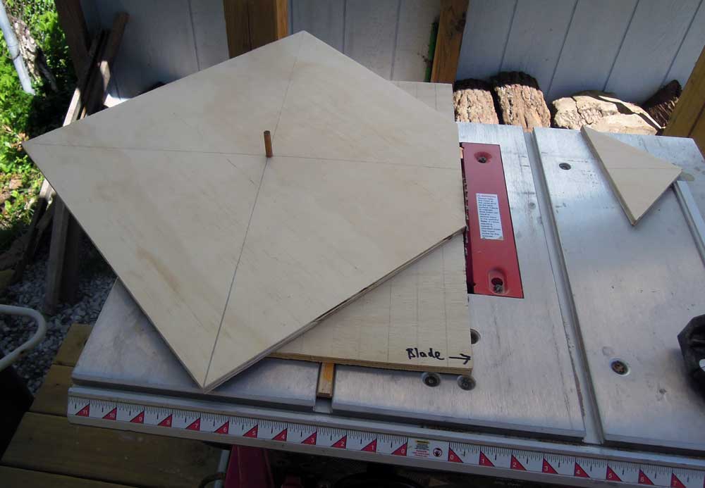
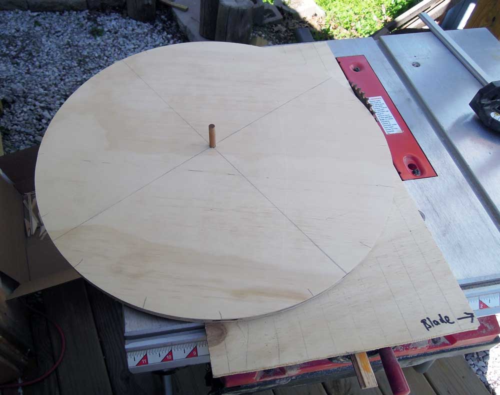
But it turns out that the disc has too much mass for the motor to turn. A lighter material is needed.
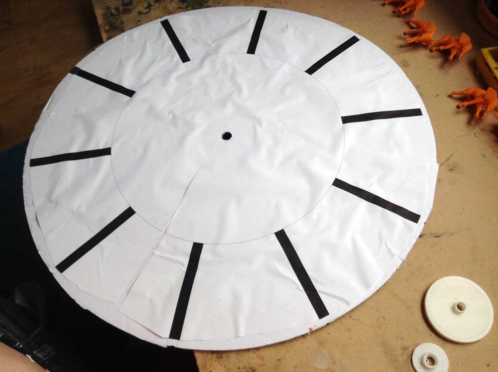
Project foam board is a better choice. Easier to cut and stiff, yet very light. And since all the objects for the actual 3D scene will be 3D printed from ABS plastic, the disc won’t carry a lot of weight. The only shortcoming so far is that the material warps easily when it gets humid.
The two 3D printed circular plastic pieces in the picture go in the middle of the disc to hold it firmly on the turntable spindle and to prevent the hole in the foam board to wear out.
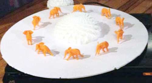
We are looking at the underside of the disc – which faces the illuminating LED and the photo-resistor. The ten black bars are the index stripes that are supposed to trigger the strobe. So this disc will support a ten frame animation in automatic strobe mode.
The Arduino is relatively easy to program. There is one segment of a “sketch” which sets up all the variables and initializes inputs and outputs. The main chunk is an endless loop. Everything that needs doing is done in there. At the moment all it needs to do is monitor the value returned by the photo-resistor and flash a control LED on the breadboard depending on whether that value is over/under a certain threshold. Later the code will become more challenging because several of the control buttons and the strobe trigger output will have to be served in the same program loop.
An open question from the beginning was what to use as a strobe light source. Full blown commercial strobe lights can be pretty pricey. Also it didn’t seem obvious how to trigger one from the Arduino. So for simple testing a 12V LED lamp was used. While not ideal, it could be directly connected to the Arduino trigger output. During the testing it turned out that, if anything, that light was too bright. Concerns that an LED wouldn’t be able to strobe fast enough were unfounded.
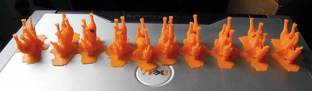
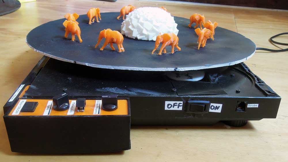
One of the things missing so far for a successful test were some 3D objects to put on the spinning disc. Thingiverse.com offers some freely download-able options. The most charming one is this set of ten walking elephants. This is how they came out of the printer.
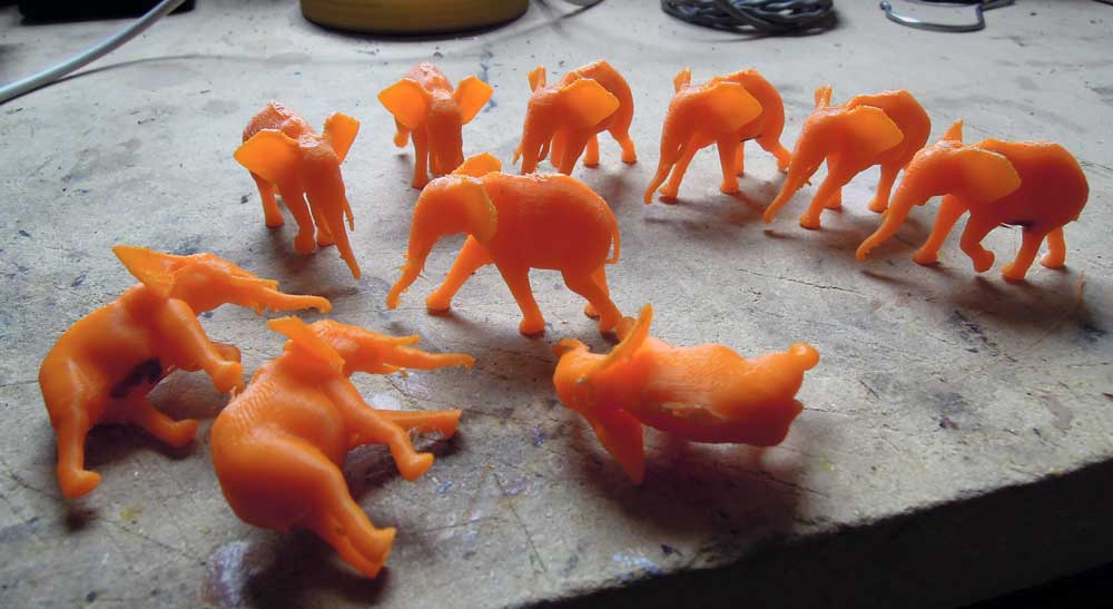
After trimming off the “raft” (the excess plastic surface) the ten elephants perform a little break-dance before they are glued to the foam board disc.
After establishing that the basic setup actually works, all the components will have to be moved inside the case. This requires replacing the Arduino UNO by it’s much tinier cousin, an Arduino Mini Pro.
Fitting everything inside the case turned out to be much more of a challenge than expected. For one all wire connections had to be made permanent. Wire lengths had to be kept as short as possible. A location for all external control knobs and buttons had to be found. The first consideration was to have an external wired control box. This should have been removable and would have required a re-purposed SCSI cable and connectors (at least 16 wires). In the end it was more feasible to 3D print a small plastic box with a removable lid and glue/screw it to the side of the record player case. This control box now contains:
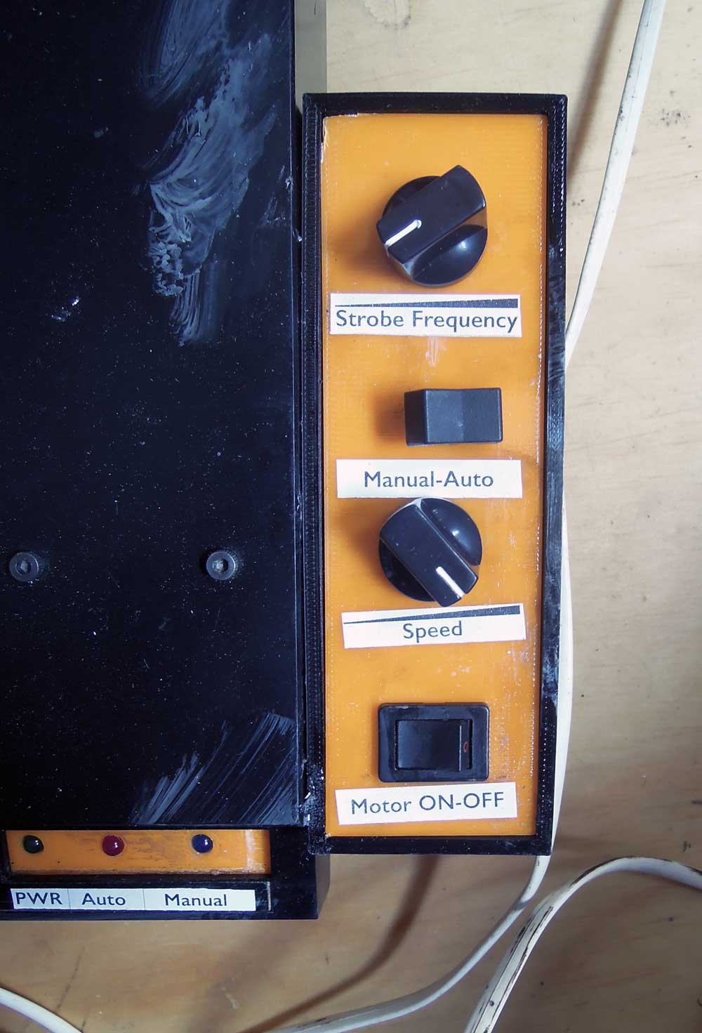
– on/off switch for the turntable motor
– potentiometer for turntable motor speed
– mode switch to set unit to run in auto strobe or manual strobe mode
– potentionmeter to set strobe light frequency when in manual mode
Three status LEDs are used for visual feedback:
– green LED to indicate that the main power is on
– red LED for automatic strobe mode
– blue LED for manual strobe mode
While the green LED is directly connected to the power supply, both the red and blue operation mode LEDs are powered through the Arduino.
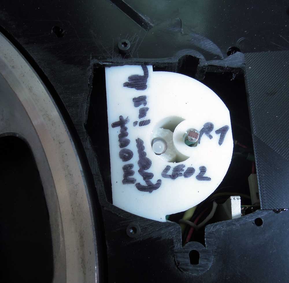
At this point the photo-resistor and white disk-illumination LED where still loosely stuck in their intended location. Some scouting around in the workshop didn’t turn up anything that could be used as a mount, so a special part was designed and 3D printed. This now fits easily into the opening, is mounted securely with screws and has a lower cavity for the LED and a higher cavity for the photo-sensor. Eventually both electronic components will be glued at the ideal height.
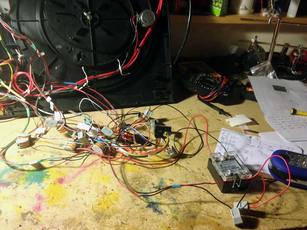
Here the rewiring with the Arduino Pro Mini is in progress. On the far right you can also see the blue LED work light which will receive a slight rewire job. Also, next to it, the big black box with the four wires sticking out and the transparent plastic cover is a relay. While the testing setup had the strobe LED directly connected to the Arduino and thus drawing power from it, it made better sense to use the Arduino to drive the relay and then have the option later on to try strobe lights of all sorts of types and power requirements. Only the trigger impulse comes from the Arduino to the relay which then switches an independent current (if necessary from a different power supply up to 110V) on or off. While not a big component it was still a bit of a challenge to fit it in the case.
Other wiring changes included getting rid of the turntable’s original power transformer and connecting the drive motor to the turntable speed potentiometer, feeding it from the PSU. Then the PSU AC feed needed to be rerouted and safely connected to a properly tension-relieved AC cord.
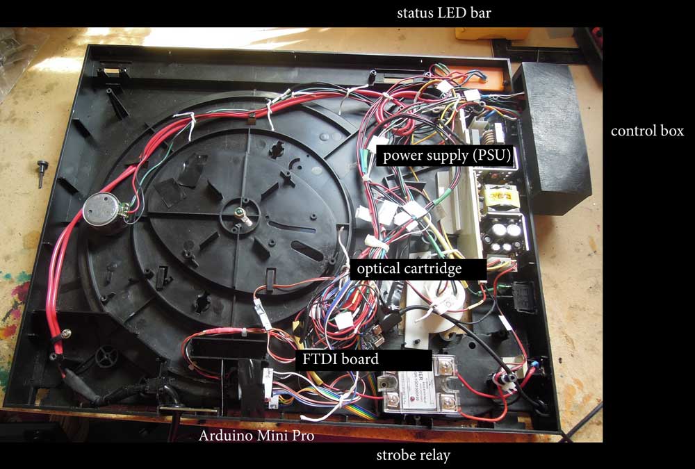
Although only planned as a future extension, an FTDI breakout board was added in this version. It allows for a computer to be connected via a USB cable. This is usually only needed for software updates. But after some testing, the optical cartridge (photo-resistor/illuminating LED combo for strobe syncing) was not working consistently. So a software update was needed and the capability to send readings from the photo-resistor to the serial monitor in the Arduino software running on a connected computer.
Side view, looking at the main power switch and to the right of it the RJ12 output jack for the strobe LED. (This picture was taken before installing the USB connection)
View from top without the scene disc. The metal turntable is from the actual record player that was butchered for this project. It has a nice mass and is driven by a belt from the drive motor. On the right next to it is the optical cartridge. Here you can also see the AC power cable and the thinner USB cable.
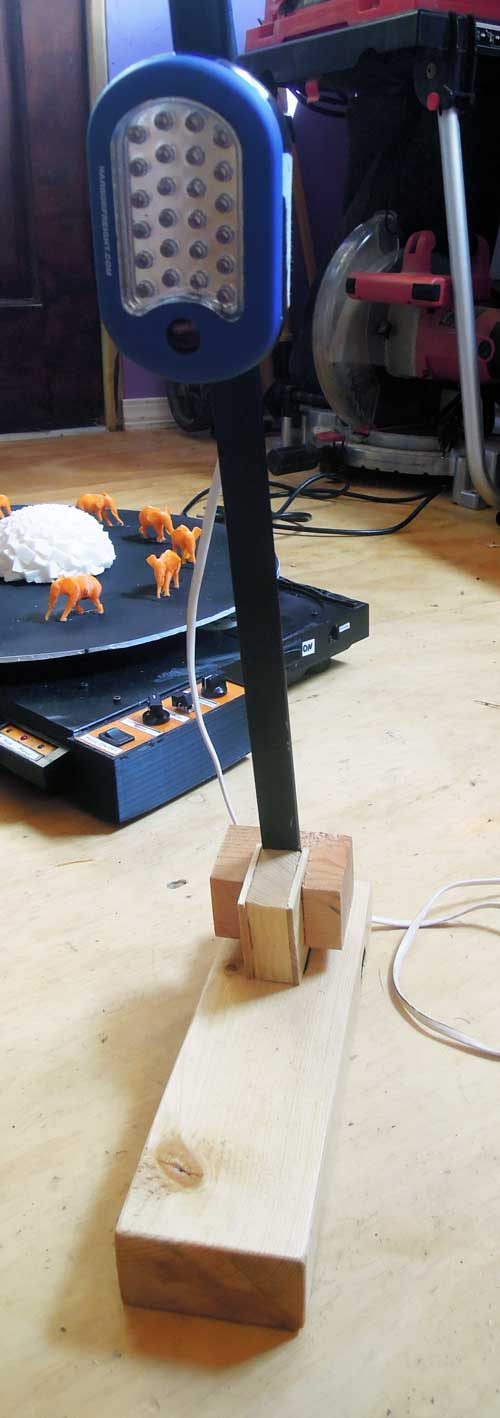
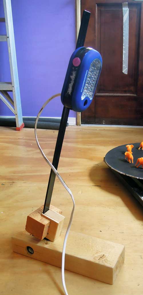
One little detail was put off until the very end and it turned out not to be so trivial. For testing the strobe LED was always held up by hand, but for permanent operation some sort of adjustable stand was needed. The original idea was to re-purpose the stand from an old desk light but in the end this simple solution worked better. Since the strobe LED has a magnet in the back a metal rod offered itself. That way the height of the strobe LED could easily be changed. The metal rod is attached to a slot in a short PVC axis in the base. To adjust the angle the wooden slider is moved along the metal rod.
The strobe LED is connected to the turntable via a pluggable telephone wire. Since correct polarity is important when wiring an LED a RJ12 connector was chosen.
This concluded the actual construction phase of the project on July 15th, 2017.